RK3588 PCIe Expansion: M.2, Multi-Port Networking, and High-Speed Peripheral Design
On Rockchip RK3588-class platforms, PCIe is the main path for adding high-speed peripherals: M.2 NVMe storage, 2.5G multi-port NICs, Wi-Fi modules, SATA expansion cards, frame grabbers, and AI accelerator cards all ride on it. Whether a design comes up on the first power-on depends on reference clock, reset, routing, power, and device-tree configuration being correct at the same time.
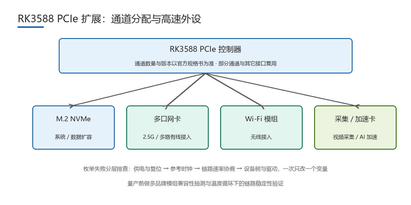
What Peripherals Can PCIe Extend?
RK3588-class platforms expose multiple PCIe lanes and Root Complexes; exact lane counts, revisions, and bifurcation options depend on the official vendor datasheet. Real projects map to a handful of patterns: M.2 NVMe for system, recording, or cache drives; 2.5G or multi-port NICs where access bandwidth and port count are insufficient; Wi-Fi/BT modules for wireless connectivity; SATA controllers to add disk bays while controlling storage cost; frame grabbers for extra cameras; and AI accelerator cards to top up inference throughput.
How Do You Implement M.2, Multi-Port Networking, and Other High-Speed Peripherals?
Pick the approach by expansion target, then define design points from it.
| Expansion target | Typical approach | Design points | Validation method |
|---|---|---|---|
| System or recording drive | M.2 M-Key to NVMe SSD | Power headroom and inrush, thermals, mounting | Sustained large-file I/O, drive drop-out and reconnect tests |
| High-bandwidth access | 2.5G or multi-port NIC (PCIe to Ethernet) | Link speed and lane allocation, reference clock, reset | Line-rate traffic, long-duration stability and temperature checks |
| Wireless connectivity | Wi-Fi/BT module (PCIe plus USB or SDIO) | Antenna placement, interference isolation, supply ripple | Throughput and packet-loss tests, coexistence checks |
| Bulk storage | PCIe-to-SATA controller for more bays | Peak supply current, cable length, bay thermals | Concurrent multi-disk I/O, drop-out and hot-plug tests |
| Compute add-on | Frame grabber or AI accelerator card | Bandwidth and power, driver and firmware compatibility, cooling | Full-load stress, extended and thermal-range runs |
The design-point column collapses into four constraints: clock, reset, signal integrity, and power. If any one is off, the symptom is often that the device enumerates but is not stable. Split acceptance into two gates: lights up, and stays stable long term.
Which Hardware Design Pitfalls Show Up Most?
- Reference clock: confirm whether it comes from the SoC output or an on-board oscillator, and whether it is dedicated or shared. Shared clocks need jitter and distribution checks, and module specs for the 100MHz reference differ.
- PERST reset: polarity, timing, and power sequencing must match the module spec. Reserve a controllable GPIO for bring-up, then freeze it into an automatic sequence for production.
- Routing length and impedance: intra-pair and inter-pair matching plus continuous impedance are basics. Connectors and vias introduce discontinuities, so the simpler the adapter board, the more stable the link.
- Power and inrush: SSDs and accelerator cards draw far more during power-up than at steady state. Size headroom and decoupling against the peak.
- Connectors and mounting: in vibration environments, check retention; poor mating durability shows up as contact failures on the line.
How Do You Debug Enumeration Failures?
Do not start by rewriting the device tree or drivers. Work layer by layer and change one variable at a time:
- Power and reset: measure rail voltage and inrush first and confirm reset timing, the most frequent root cause;
- Reference clock: use a scope to confirm the clock is present and meets frequency and level requirements;
- Link negotiation speed: check whether the link trained at a downgraded rate, which usually points to signal integrity or routing;
- Device tree nodes and drivers: verify controller nodes, clock and reset references, and power descriptions, then driver versions;
- Firmware revision: uboot and kernel PCIe support differences can change results on identical hardware.
Layered debugging turns guesswork into localization. Re-test after each single change and record results, so the problem converges to a cause rather than a few unexplained fixes.
How Should Device Tree, Drivers, and Production Validation Be Arranged?
For device tree and drivers, describe clock, reset, power, and lane allocation correctly under the controller node, then attach the right child node for the module so the system enumerates it as intended. Exact syntax and parameter values should follow the platform BSP documentation and mainline kernel references; copying another project's device tree is risky. Prefer existing in-kernel drivers, and make custom drivers cover hot-plug and error recovery.
Production validation should cover three areas: compatibility sampling across board variants and module brands; mating durability after repeated insertions; and thermal cycling within the target operating range to catch link down-negotiation or drive drops, a frequent source of field returns. Record material lot and firmware revision for traceability.
FAQ
- Q1: How many PCIe devices can RK3588 support at once?It depends on available lanes and Root Complex partitioning; check the official datasheet and BSP. Plan each link with its own clock and reset.
- Q2: An M.2 SSD is not detected. What should I check?Go layer by layer: power and reset, reference clock, link negotiation speed, device tree and drivers, then firmware revision, changing one variable at a time.
- Q3: The device enumerates but data transfer is unstable. Why?Signal integrity or peak power is the usual cause. Check whether the link down-negotiated, then verify power headroom and decoupling.
- Q4: What should production validation focus on for PCIe?Compatibility sampling across board variants and module brands, mating durability, and link stability under thermal cycling, recording material lot and firmware revision throughout.
Hongyin Tech provides full-stack SoM/SBC customization on Rockchip & HiSilicon platforms with Android/Linux. Engineers respond within 1 business day.
Get a Free Quote →